


Working Principles of Chamfering Machines: Gear vs Belt Drive
Gear-Driven Systems: Precision and High Torque Delivery
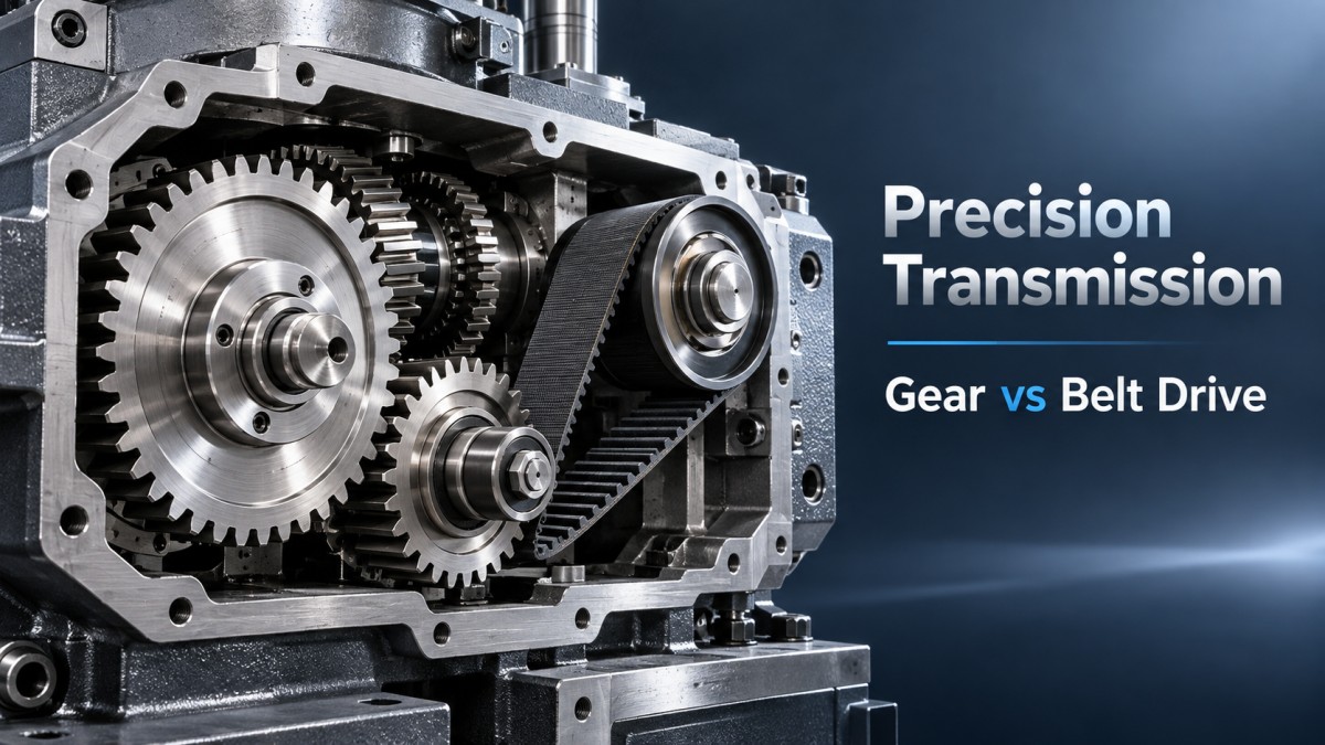
Gear drives rely on the direct mechanical engagement of toothed wheels to transmit power from the motor to the spindle. In the context of a chamfering machine, this direct, positive contact ensures zero slippage, providing highly consistent rotational speed and maximum torque transfer to the cutting or deburring tools.
The primary advantage of a gear-driven system lies in its rigidity. When processing thick carbon steel plates or performing aggressive edge chamfering, the spindle must maintain its position and speed despite high cutting resistance. Gear drives excel here, maintaining tight tolerances and ensuring that the edge geometry remains perfectly consistent over long production shifts. Because there is no elastic deformation in the power transmission, the machine can handle heavy material removal without losing synchronization.
However, this mechanical rigidity comes with specific operational trade-offs. Metal-to-metal contact inherently generates noise and heat. More importantly, gear systems lack natural shock absorption. If a chamfering cutter unexpectedly catches on a hard slag inclusion or a warped workpiece edge, the sudden spike in resistance is transmitted directly through the gears. Without a mechanical slip mechanism, this shock can damage the spindle bearings, strip gear teeth, or overload the motor. Consequently, gear-driven machines require strict lubrication schedules, regular vibration monitoring, and robust overload protection circuits.
Belt-Driven Systems: Flexibility and Shock Absorption
Belt drives transmit power through friction between a flexible belt and pulleys. This inherent flexibility introduces a degree of elasticity into the transmission system, fundamentally changing how the machine interacts with the workpiece.
The most significant benefit of a belt drive in metal finishing is its ability to act as a mechanical fuse. If a deburring brush or a chamfering tool encounters an unexpected hard spot, the belt will slip. This slippage protects the motor and spindle from catastrophic mechanical shock, significantly extending the lifespan of the core drive components. Additionally, belt drives operate quietly, do not require lubrication, and are highly effective at dampening high-frequency vibrations, which is crucial for achieving uniform surface finishes on aluminum or stainless steel.
The limitation of belt drives is their susceptibility to slippage under heavy, continuous loads. In aggressive chamfering scenarios, this can lead to inconsistent edge profiles and reduced material removal rates. Furthermore, belts stretch over time and are sensitive to environmental contaminants. In metal processing environments, fine metallic dust can accumulate on the pulleys, accelerating wear and requiring periodic tension adjustments to maintain precision.
Matching the Drive to the Application
Technical evaluators should not view gear and belt drives as mutually exclusive choices for the entire machine, but rather evaluate them based on the specific processing station and operational goal.
- Heavy Chamfering and Thick Plate Processing: If the primary task is forming precise, large R-arcs on thick plates (e.g., 20mm+ carbon steel) where edge geometry must remain perfectly consistent, a gear-driven spindle is typically the baseline requirement. The high torque and rigidity are non-negotiable here.
- Deburring, Edge Rounding, and Surface Finishing: If the operation focuses on removing micro-burrs from laser-cut edges, descaling, or applying a fine brushed finish, belt-driven systems offer the necessary speed, flexibility, and shock absorption. The risk of tool damage from hidden slag is mitigated by the belt's slip capability.
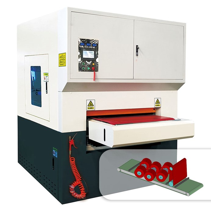
In modern automated finishing solutions, the distinction is often blurred by multi-station designs. Complex workflows rarely rely on a single transmission logic. For instance, comprehensive equipment like the Polishing DV-RPRF integrates multiple processing stages—such as coarse grinding with abrasive belts, precision edge treatment with roller brushes, and final polishing. In such configurations, the transmission logic is adapted to each specific station: belt drives might handle the flexible sanding units to absorb shocks from uneven cut edges, while geared or direct-drive mechanisms ensure the rigid consistency required for the final polishing rollers to achieve a uniform #4 finish.
Maintenance Realities and Lifecycle Costs
When evaluating these systems, looking beyond the initial purchase price to the total cost of ownership is critical. Gear systems demand predictive maintenance. Oil analysis, gear wear inspection, and vibration monitoring are necessary to prevent unexpected downtime. However, if maintained correctly, the core geared components have a very long lifecycle.
Belt systems have lower routine maintenance but higher consumable costs. Belts and pulleys are wear items. Even in facilities utilizing advanced environmental controls, such as a 6.6KW explosion-proof wet dust collector to capture airborne particles during operation, microscopic abrasives can still infiltrate the drive housing. This environment accelerates belt wear, meaning replacement intervals must be factored into the operational budget. Furthermore, the conveyor system transferring the workpieces—often relying on wear-resistant belts and variable-speed frequency control—adds another layer of belt maintenance to the overall machine lifecycle.
Ultimately, the choice between gear and belt drives in a chamfering machine is a trade-off between rigid precision and flexible protection. By mapping the specific material thickness, burr severity, and edge tolerance requirements against these mechanical characteristics, technical evaluators can specify a transmission setup that maximizes both throughput and equipment longevity.
NAVIGATION
Send Us A Message
Please give us a message